Guide to avoiding pitfalls throughout the entire process of wire drawing machine reducer, even beginners can get it right in one go
1、 Selection stage: precise matching, rejecting "empiricism"
Selection is the first hurdle in the application of wire drawing machine reducers, and it is important to avoid blindly making decisions based solely on motor power. The following core dimensions must be comprehensively considered:
1. Deep calculation of torque and load characteristics
The most common mistake beginners make is to only focus on power and ignore torque. The wire drawing machine often experiences significant impact loads during the start-up and threading process. When calculating the required output torque, it is not only necessary to meet the static torque demand at maximum load, but also to reserve a safety factor of 20% to 30% (it is recommended to take 1.5 times or more for impact conditions). If the torque margin is insufficient, it can easily lead to gear breakage or early bearing failure of the gearbox; On the contrary, blindly pursuing large margins not only increases procurement costs, but also leads to low transmission efficiency due to the "big horse pulling small car".
2. Scientific setting of transmission ratio and speed ratio
The transmission ratio of the reducer needs to be accurately calculated based on the rated speed of the motor and the final working speed of the wire drawing machine drum. For example, when the motor speed is 1500 revolutions per minute and the required drum speed is 600 revolutions per minute, the required transmission ratio is approximately 2.5. It should be noted that the higher the speed ratio, the better. If a worm gear reducer is used and the speed ratio is greater than 40, its transmission efficiency will significantly decrease. In this case, it is recommended to use a combination of planetary gears or helical gears to ensure the overall transmission efficiency.
3. Adaptation of structural form and working environment
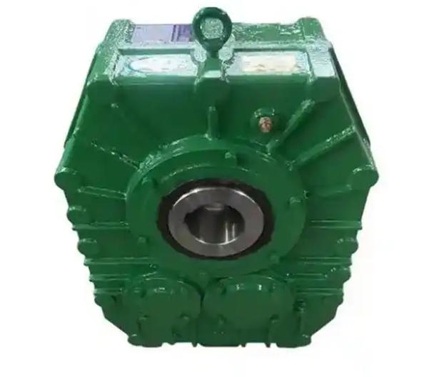
Drawing machines usually require reducers with small size and strong load-bearing capacity, and planetary gear reducers or hard toothed helical gear reducers are ideal choices. At the same time, it is necessary to adapt according to the workshop environment: if it is in a dusty, humid, or foggy drawing coolant environment, a shell with a protection level of IP65 or above must be selected and equipped with a corrosion-resistant coating; For high-precision wire drawing equipment, attention should also be paid to the backlash of the reducer. It is recommended to choose precision models with backlash less than 5 arc minutes to ensure constant tension of the wire.
2、 Installation phase: Standardized operation, strict control of "even the slightest difference"
No matter how good the gearbox is, if it is not installed properly, it will also become "scrap metal". Every detail during the installation process is related to the ultimate lifespan of the equipment.
1. Basic rigidity and alignment calibration
The flatness error of the installation base must be controlled within ≤ 0.1mm/m. For high-power reducers, it is recommended to pour concrete foundation and perform secondary grouting to prevent bolt loosening caused by vibration. When connecting the coupling, it is strictly prohibited to use violent assembly methods such as hammering. Laser alignment must be used for calibration to ensure that the radial deviation is ≤ 0.05mm and the angular deviation is ≤ 0.02mm. A misalignment of 0.1mm may shorten the bearing life by 60%, and precise alignment is the key to reducing the failure rate.