What Precautions Must Be Taken When Installing and Maintaining the WHC210 50 4F Worm Gear Reducer?
The successful operation of the WHC210-50-4F worm gear reducer hinges on two fundamental principles: ensuring perfect coaxiality and secure fixation during installation, and maintaining rigorous lubrication management and component inspection during operation. To guarantee optimal performance and extend the equipment's lifespan, the following specific precautions must be strictly adhered to.
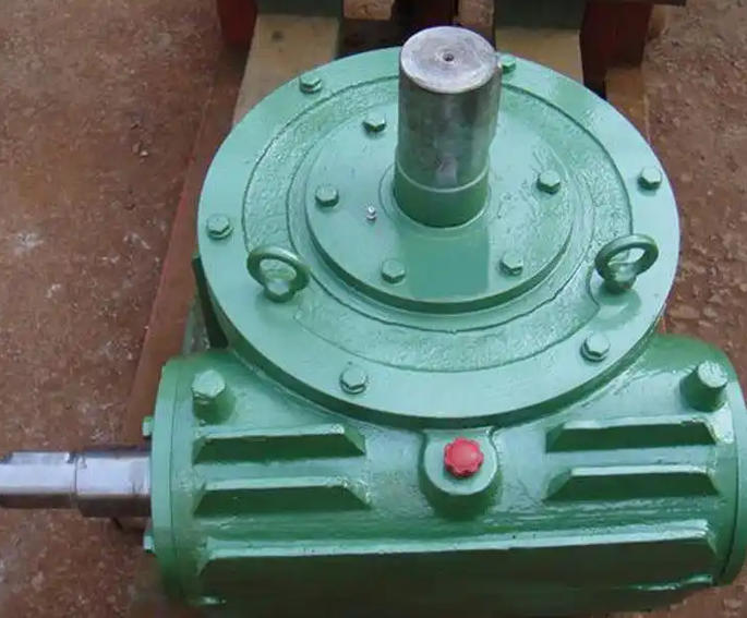
Installation Precautions
Pre-Installation Preparation:
Before mounting the reducer, conduct a thorough visual inspection of the casting for any bumps, cracks, or structural defects. Manually rotate the input and output shafts to confirm they turn smoothly without any jamming or resistance. Additionally, meticulously clean the installation surface, removing all oil stains, burrs, and debris to prevent uneven stress distribution once the unit is secured.
Alignment Requirements:
When connecting the motor to the reducer, precision alignment is critical. The coaxiality error between the two shafts must be strictly controlled to ≤ 0.2mm, and the end face runout should not exceed 0.1mm. It is highly recommended to use elastic couplings, as they effectively absorb minor installation deviations and protect the bearings and gear tooth surfaces from excessive impact loads.
Fixation and Orientation:
Secure the reducer base using high-strength bolts, and always incorporate anti-loosening mechanisms such as spring washers or lock nuts to prevent loosening caused by operational vibrations. Install the unit strictly according to the nameplate specifications. Ensure the lubricating oil level is correct, and never install the reducer upside down or at an angle exceeding 15°.
Pipeline and Sealing Inspection:
If the system involves lubrication or cooling pipelines, verify that all interfaces are tightly sealed and completely leak-free. Before connecting the power, manually rotate the input shaft one final time to ensure there is no binding or abnormal noise. Only after this confirmation should the trial operation commence.
Maintenance Precautions
Lubricating Oil Management:
Proper lubrication is the lifeblood of the reducer. Replace the lubricating oil after the first 500 hours of operation to remove initial break-in wear particles. Thereafter, change the oil every 2,000 to 3,000 hours, or at least once a year. Use 220# or 320# extreme-pressure industrial gear oil, and maintain the oil level precisely at the centerline of the oil window to prevent overheating caused by insufficient lubrication or excessive churning.
Regular Inspection Focus:
Implement a strict inspection schedule:
-
Weekly: Check the oil level and monitor the operating temperature. The normal working temperature should be ≤ 80℃; if it exceeds 90℃, immediately shut down the machine for troubleshooting.
-
Monthly: Inspect all bolts for proper tightness and check seals for any signs of leakage.
-
Semi-Annually: Evaluate tooth surface wear and bearing clearance. If pitting, adhesion, or abnormal bearing noise is detected, promptly repair or replace the affected components.
Adaptation to Working Conditions:
For harsh environments such as mines or chemical plants, install protective covers over the gearbox to prevent dust and moisture ingress. If the reducer will be shut down for an extended period (more than one month), run it without load for 10 minutes before shutdown, drain the old oil, and refill with fresh oil prior to restarting to prevent internal corrosion.
Fault Handling Principles:
Never ignore warning signs. If abnormal vibration or increased noise occurs, immediately stop the machine to identify and resolve issues such as coaxiality deviation, loose bolts, or gear wear. Forced operation under overload or low-oil conditions is strictly prohibited, as it will cause irreversible, permanent damage to the gears and bearings.