LD19-35-55KW Cycloidal Reducer Installation Requirements & Warnings
When installing the BLD19-35-55KW cycloidal pinwheel reducer, three core areas must be prioritized: stable foundation, precise transmission alignment, and compliant lubrication. This prevents operational vibration, part abrasion, and shortened service life resulting from improper installation. The detailed precautions fall into five key modules.
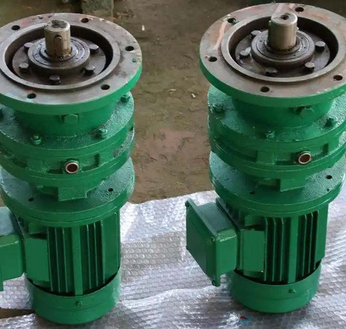
1. Pre-installation Preparation: Inspect Equipment and Environment to Eliminate Hidden Risks
Pre-installation checks help avoid faults that are hard to remedy afterward. Three critical points require confirmation:
-
Equipment appearance and component inspection: After unpacking, examine the reducer housing and output shaft for transportation deformation. Rotate the output shaft manually to check for jamming or unusual noise, which indicates whether internal parts such as cycloidal wheels and pin teeth have shifted due to vibration. Meanwhile, cross-verify the model BLD19-35-55KW against installation drawings to confirm matching motor power, reduction ratio and load demands.
-
Foundation and environmental requirements: The mounting base must be flat and robust. Concrete foundation strength shall not be lower than C20, with surface flatness tolerance ≤0.1mm/m measured by spirit level. Drainage channels need to be reserved under the base to prevent oil and water buildup. Ambient temperature should range from -10℃ to 40℃. Keep the unit away from dust and corrosive gas to protect components from corrosion.
-
Tool and accessory preparation: Prepare torque wrenches for accurate bolt tightening, spirit levels with precision ≥0.02mm/m, dial indicators for coaxiality calibration. Also get qualified lubricant (normally 46# or 68# industrial gear oil, refer to the official manual) and sealant for flange joint sealing in advance.
2. Foundation Mounting: Secure Firmly to Prevent Displacement and Reduce Running Vibration
The 55KW unit is a high-power variant with obvious vibration during operation, so rigid foundation fixing is essential. Follow these steps:
-
Positioning and leveling: Hoist the reducer onto the foundation and adjust its position per installation drawings to match the center height of the output shaft with connected load equipment like fans or pump bodies. Use a spirit level on the housing flat surface and output shaft end to check levelness. Adjust by adding or removing base shims to keep horizontal error ≤0.2mm/m.
-
Bolt fastening: Adopt anchor bolts of strength grade ≥8.8. Tighten them diagonally in 2 to 3 incremental passes. Final torque shall comply with manual specifications (M24 bolt torque is generally 300–350N·m). Recheck levelness after tightening to rule out equipment shift during fastening.
3. Transmission Connection: Maintain Coaxiality to Eliminate Extra Loads
Alignment of the transmission connection directly impacts bearing service life, and coaxiality error must be strictly controlled:
-
Coupling specifications: For elastic couplings, use a dial indicator to measure radial and face runout. Radial tolerance ≤0.1mm and face tolerance ≤0.05mm. If rigid couplings are applied, keep the error within ≤0.03mm. Misalignment will impose extra radial load on bearings and lead to overheating or premature wear.