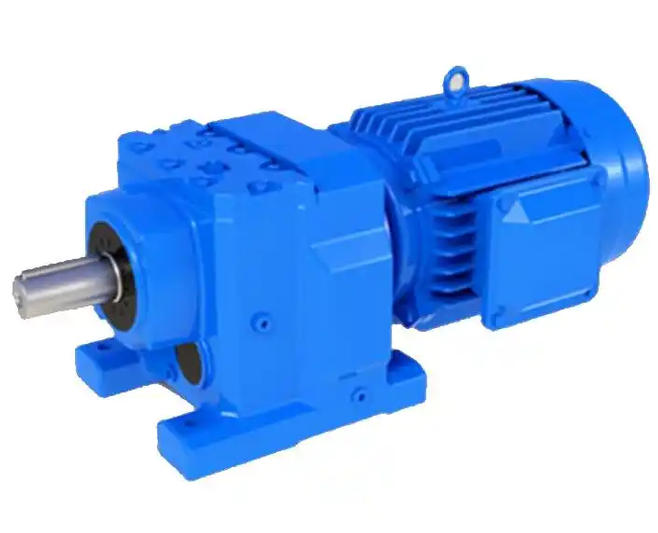
How to verify the load fluctuation of the R17 gear reducer
1、 Core test bench construction and sensor selection
R17 has a small volume and low inertia, and the precision requirements for the test bench are higher than those for large reducers. It is recommended to use closed-loop power loading testing method, where the driving motor simulates the prime mover and the load motor simulates the working machine.
Torque and speed sensor: High precision non-contact sensors (recommended accuracy ≥ 0.5 level) must be installed at both the input and output ends to synchronously collect instantaneous speed and torque, which is the basis for capturing small fluctuations.
Data collection frequency: It is recommended to sample at a frequency of ≥ 1kHz to ensure the capture of impact fluctuations and transient responses during gear meshing.
Coaxiality calibration: R17 is extremely sensitive to installation deviations, and the coaxiality of the input/output shaft needs to be controlled within ≤ 0.05mm to avoid distortion of test data caused by additional loads during installation.
2、 The core testing process for load fluctuation verification
According to GB/T 16444 "Test Methods for Reducer" and industry practices, it is recommended to conduct the load fluctuation verification of R17 in the following four stages:
1. No load baseline test (running in and benchmark establishment)
Gradually increase the speed at rated speed (run at 30%, 50%, and 80% for 10 minutes each), and confirm that there is no lag or jamming during continuous operation for 30-60 minutes.
Record the torque baseline, vibration spectrum, and noise values under no-load conditions as a benchmark for comparing subsequent load fluctuations.
2. Gradual steady-state loading test (to verify transmission stability)
Gradually increase the rated load by 25% → 50% → 75% → 100%, and run steadily for 30 minutes at each level of load.
Core monitoring indicators: Under 100% rated load, the allowable deviation of output torque is -5% to+10%, and the torque fluctuation rate during loading should be controlled within ≤ 1% to 3%. If the fluctuation exceeds the standard, it usually indicates gear meshing error, bearing assembly deviation, or insufficient box rigidity.
3. Alternating load and dynamic response testing (simulating real working conditions)
R17 is commonly used in conveying, mixing, or automation equipment, often facing start stop and forward/reverse rotation. Simulate actual working conditions for forward and reverse cyclic loading (such as 10-30 seconds/cycle), monitor torque fluctuation rate and backlash changes.
Use spectral analysis (Fourier transform) to decompose torque signals into frequency domain components and identify periodic fluctuation sources (such as gear meshing frequency, shaft frequency, etc.).
4. Short term overload verification (checking safety margin)
Conduct overload tests for 15 minutes at 110% rated load and 10 minutes at 125% rated load.
Focus on observing whether there is a sudden change in torque fluctuation and temperature rise under overload conditions, in order to verify the fatigue strength of gears and shafts.
3、 Key judgment indicators and abnormal investigation
During the verification process, in addition to focusing on torque data, it is also necessary to comprehensively determine the health status of R17 based on the following indicators: