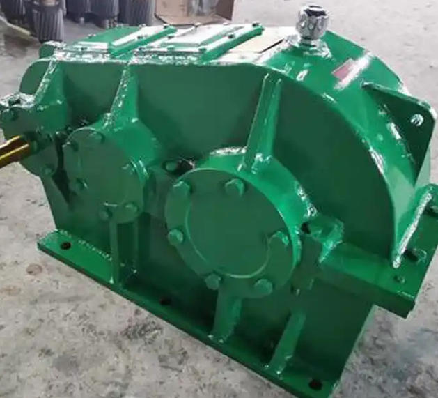
How to Adjust the Shaft Misalignment of the ZL75-31.5-1 Soft Tooth Surface Gearbox
1、 Preliminary preparation
Tools: Prepare laser centering instrument/dial gauge, feeler gauge, 0.1~0.5mm stainless steel adjusting gasket, torque wrench, precision level.
Preprocessing: Clean the burrs and oil stains on the installation foundation surface, check that the levelness of the reducer base is ≤ 0.1mm/m, confirm that the coupling is not worn or deformed, and reserve 1-2 turns of looseness of the motor foot for easy displacement adjustment.
2、 Adjustment steps
1. Rough centering positioning
Use a ruler to lean against the outer circle of the two halves of the coupling, and preliminarily align the height difference of the outer circle by adding or removing the foundation gasket of the reducer.
Measure the end face spacing around the coupling with a caliper, adjust the displacement bolt on the motor side to control the end face clearance difference within 0.2mm, and keep the two shafts within the adjustable reference range.
2. Precise alignment calibration
Dial gauge method: Fix the radial gauge and axial gauge at a 90 ° angle on the coupling, rotate the two shafts synchronously 360 °, record the reading every 45 °, and the valid reading difference is ≤ 0.02mm for 3 consecutive turns. Calculate the radial and angular deviations based on the readings, and gradually bring the deviations within the tolerance range by adding or removing foot pads and moving the motor laterally.
Laser centering instrument method: Fix the transmitting and receiving units on both sides of the axis, rotate the axis to 0 °, 90 °, 180 °, and 270 ° to collect data, and the instrument automatically generates a deviation report. Adjust the device position according to the prompts, with an accuracy of ± 0.001mm and an efficiency more than three times higher than manual measurement.
3. Thermal expansion compensation
The compensation amount for the carbon steel shaft is calculated based on a linear expansion coefficient of 11.5 × 10 ⁻⁶/℃. During cold alignment, the center of the reducer side shaft is slightly lower than the center of the motor/load shaft by 0.1-0.15mm to offset the secondary deviation caused by the upward movement of the axis after heating up during operation.
4. Tightening and re inspection
Tighten the anchor bolts evenly 2-3 times in diagonal order, with torque error controlled within ≤ 5%.
After tightening, retest the coaxiality to confirm that there is no rebound in the deviation; Run without load for 1-2 hours, wait for the equipment to cool down, and finally recheck the accuracy of the axis line to ensure that the deviation change does not exceed 50% of the original tolerance.